How Do You Test an Antenna for Space?
International Standards and the TGGS Laboratory Work Behind Our S-band Antenna
Inside the signal tests, the environment tests, and the standards that confirm space readiness.
Space is the hardest place to work
Space is a harsh place. A rocket launch shakes the satellite with strong vibration. Sunlight heats one side to high temperature. The shadow side drops to deep cold. There is no air to carry heat away. Radiation passes through the hardware every day.
A part that works perfectly on a lab bench can fail in orbit. Every space antenna must pass tough tests before flight. At mu Space, our S-band Patch Antenna is tested in two main areas: signal performance and space environment.
The core idea of space testing Test the antenna the way space will treat it. Measure every important number. Repeat with the right equipment, the right method, and the right standards. Write everything down. |
Part 1. Signal performance testing
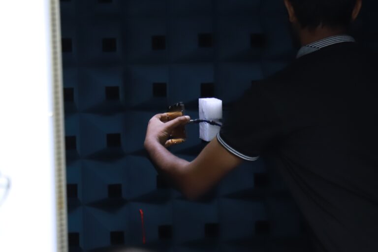
Signal tests check how well the antenna sends and receives radio waves. These tests happen in a special quiet room called an anechoic chamber. The walls of this chamber absorb radio waves so nothing bounces back. The result is a clean, honest measurement.
Our signal tests were performed at the High Frequency Systems Laboratory (HFS), part of the Sirindhorn International Thai-German Graduate School of Engineering (TGGS) at King Mongkut’s University of Technology North Bangkok. The lab carries out antenna measurements using internationally recognized methods and calibrated equipment.
The four main signal tests
- Return loss and VSWR. How much of the signal enters the antenna. Good antennas keep this loss low. Our measured S11 stays under -10 dB across the full band of 2.025 to 2.29 GHz.
- Antenna gain. How strong the signal travels in the main direction. Our High-Gain version measured 7.54 to 7.68 dBi at boresight. This passes the contractual target of 7.5 dBi.
- Radiation pattern. The shape of the signal coverage in 3D space. Our antenna has a half-power beamwidth of about 70 degrees, a good shape for satellite-to-ground links.
- Axial ratio. A check for clean circular polarization. A value under 3 dB is excellent. Our antenna passed this test, confirming true RHCP behavior.
The equipment behind the numbers
- Anechoic Chamber: Atenlab A6 direct far-field chamber at TGGS.
- Network Analyzer: Keysight E5063A, a trusted benchmark tool in the RF industry.
- Calibration Kit: Keysight 85052C, for traceable and accurate measurements.
- Test Method: Direct far-field, a standard method recognized by IEEE antenna measurement practice (IEEE Std 149).
The TGGS lab issued a formal certification letter for our August 2022 measurement campaign. The letter confirms the measurement followed correct scientific principles of antenna test measurement, and that the work was planned and executed by qualified engineers.

Part 2. Space environment testing
After signal tests, the antenna must survive the physical stress of launch and orbit. This is called qualification testing. Our qualification profile follows international space standards from the European Space Agency (ECSS) and NASA (GEVS).
The tests in the qualification profile are:
- Random vibration. Shakes the antenna with the same pattern a rocket creates during lift-off.
- Sinusoidal vibration. A slow, sweeping shake that reveals weak resonances in the structure.
- Pyroshock. A sharp mechanical impact, similar to stage separation inside a rocket.
- Thermal cycling. Heats and cools the antenna many times, copying the day-and-night cycle in orbit.
- Thermal vacuum. Places the antenna in a cold vacuum, checking outgassing and performance under space conditions.
- Corona and arc discharge. Confirms the antenna will not create electrical arcs at low-pressure altitudes.
These tests together prove that the antenna can survive the journey from the launch pad to orbit, and then keep working for the full mission.

The international standards we follow
Using recognized standards means the antenna is tested the same way space-grade parts are tested around the world. The main references in our test profile:
Standard | Purpose |
|---|---|
ECSS-E-ST-10-03C | Testing of space segment products (ESA) |
GSFC-STD-7000A (GEVS) | General Environmental Verification Standard (NASA GSFC) |
NASA-STD-7001 | Payload Vibroacoustic Test Criteria |
NASA-STD-7003 | Pyroshock Test Criteria |
ECSS-Q-ST-70-02 | Thermal vacuum outgassing screening for space materials |
IEEE Std 149 (reference) | Standard Test Procedures for Antennas (signal performance) |
Behind the lab door
A photo from the TGGS chamber tells the story of careful work. The antenna sits on a low-dielectric EPE foam mount. A harness connects it to the network analyzer. A rotator turns the antenna through full angles to capture the complete radiation pattern. The engineers align, calibrate, record, and review every measurement.
Seven antennas were tested in the 2025 delivery campaign: three Low-Gain (Standard) units and four High-Gain units. Four of them passed every technical requirement of the delivery contract. Every result was documented, every result can be traced.
What certified testing gives our customers Evidence of performance. Proof of space readiness. A clear record of which standard was used and how the measurement was done. Space customers value this more than any marketing claim. |
mu Space engineering, international trust
A tested antenna is a trusted antenna. The space industry runs on evidence, not on claims. Every certified lab, every recorded number, and every international standard we follow adds to that evidence.
Our S-band Patch Antenna has moved through simulation, prototype, and full signal measurement. It has been inspected by a certified antenna facility. It is now ready for the full qualification test profile. This is how Thai engineering earns international trust.
At mu Space, our approach stays simple: design carefully, test honestly, document everything. That is how good space hardware is made